
Security
Can connected lighting controls work with existing fixtures?
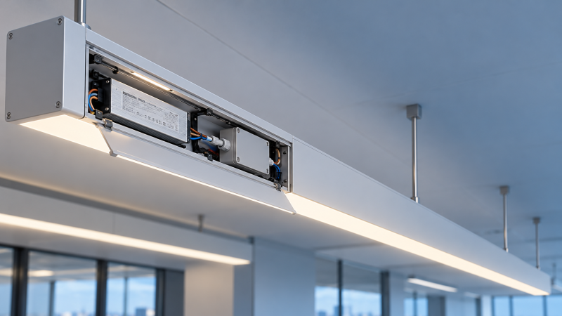
Yes. Connected lighting controls can work with existing fixtures when the control method matches the installed driver or ballast, the available wiring, and the required lighting behavior. A fixture does not necessarily need a built-in radio: an external relay, dimming controller, or replacement driver can provide a connection. However, a controller that switches the circuit successfully will not automatically provide dimming, individual fixture control, or reliable status feedback.
The first decision is the required level of control. If an entire circuit only needs scheduled on/off operation, a compatible networked relay may be enough. If fixtures must dim independently, respond to occupancy, or report their status, the driver interface and physical layout become much more important. A retrofit is viable only when those requirements can be met without exceeding electrical ratings or compromising the fixture’s safety and performance.
Start with the driver or ballast, not the lamp label
Identify the control gear inside each representative fixture. Record its model, input voltage, load characteristics, and any control terminals or markings. LED fixtures may use a separate driver, an integrated driver, or a replaceable lamp with electronics built into its base. Fluorescent fixtures use ballasts whose switching and dimming capabilities vary. Fixtures that look identical from the outside can contain different control gear after years of maintenance.
A label stating that a lamp or fixture is “dimmable” is not a complete compatibility statement. It does not identify whether the equipment accepts phase-cut dimming, a 0–10 V signal, a digital control interface, or another method. The controller and driver documentation must agree on the interface and operating conditions. A mismatch can produce flicker, limited dimming range, audible noise, failure to start at a low setting, or premature shutdown.
Also distinguish the driver’s power input from its control input. Some drivers remain energized while a separate low-voltage or digital signal changes light output. Others are controlled by modifying or interrupting the mains supply. Connecting a controller to the wrong terminals, or assuming that all dimming inputs behave alike, can damage equipment or create unsafe wiring.
Choose the retrofit route that matches the desired behavior
A relay is often the simplest route for shared on/off control, but its published wattage rating alone does not establish suitability. LED drivers can draw a brief inrush current at energization, and a circuit with many drivers can stress relay contacts even when its steady-state load is modest. Review the controller’s permitted load type and capacity against the actual fixture population; a contactor or a different switching arrangement may be needed.
Replacing a driver opens more control options, but requires a closer engineering review. The output current or voltage, power range, dimming characteristics, and connection method must suit the LED module. Physical fit is only part of the assessment: a driver installed in a confined housing must also operate within its specified temperature limits. Modifications can affect the fixture’s original listing or approval, so the proposed assembly and local requirements need review before work begins.
Control wiring determines the scope of the installation
Existing lighting circuits often provide switched line voltage but no separate path for dimming signals. A 0–10 V retrofit, for example, requires a compatible driver and a suitable control connection between the controller and each controlled group. Whether existing cable can be reused depends on its conductors, insulation, routing, and the applicable installation rules. The presence of spare wires does not establish that they are appropriate for a new control circuit.
Wireless control can reduce new signal cabling, but it does not eliminate the need for power. A connected lamp or fixture generally needs an available supply to receive commands. If an existing wall switch cuts that supply, remote operation and scheduled control stop until power is restored. The wall control strategy therefore needs to be designed together with the networked devices.
Space is another practical constraint. An external module must fit in an approved location with adequate access, enclosure protection, and heat dissipation. Metal housings and above-ceiling installations can also affect radio coverage. A controller that works on a bench may behave differently once enclosed and surrounded by building materials.
Group control versus individual addressability
A circuit-level relay sees a group of fixtures as one load. It cannot independently dim a fixture beside a window or identify which luminaire has failed. Individual control requires an addressable device at each fixture or an architecture that reaches each driver separately. That distinction changes the amount of hardware, commissioning work, and ongoing device management.
Some existing digital control installations already support addressable fixtures, making a gateway a possible route to connected operation. Confirm the gateway’s supported commands and the capabilities of the installed control gear. A gateway may expose group dimming while offering limited access to diagnostics, scenes, or fixture-specific data.
Interoperability has several layers
A shared protocol name is a useful starting point, not proof that two devices will deliver the same features together. Establish what communicates over each link: the driver’s dimming interface, the local control network, and any connection to a building management system. These are separate interfaces, and a compatible radio does not make an incompatible driver dimmable.
Review the functions needed after installation: discovery, grouping, schedules, occupancy response, scene recall, status reporting, and fault indication. Verify whether configuration and control require a gateway, an internet connection, or a particular management application. Clarify what remains available if the gateway, network, or external service is unavailable.
Security and maintenance deserve attention when lighting controls join an operational network. Device authentication, access permissions, software updates, and the ability to remove or replace a failed device affect long-term support. A locally controlled system may be appropriate where continuous internet access is undesirable, but local operation should be demonstrated for the specific functions required.
Use a representative fixture to expose compatibility problems
A small installation trial is most useful when it includes the variations found on site: different driver models, a heavily loaded circuit, fixtures at the edge of expected radio coverage, and any locations with unusual enclosures. Test normal operation as well as recovery after a power interruption. Record the actual equipment identifiers and firmware or configuration versions so that the result remains traceable.
For dimming, observe the full intended range. A fixture that responds at mid-level may flicker near minimum output, take too long to start, or fail to turn off completely. Confirm whether the application requires a true off state or whether a low dimmed level is acceptable. When several fixtures share a control channel, compare their output: different drivers can respond unevenly to the same signal.
Test occupancy and daylight behavior in the installed environment. Sensor placement, obstructions, daylight contribution, and the area assigned to each control zone can matter more than nominal sensor coverage. A sensor controlling a large shared circuit may leave occupied areas dark or keep an entire zone lit because one part remains occupied.
During the trial, separate communication faults from electrical or driver faults. If a fixture fails to respond, local controller status, supply voltage, signal wiring, and driver behavior provide different clues. Repeatedly replacing network devices will not solve a dimming-interface mismatch; changing the driver will not repair poor radio coverage.
Safety, emergency operation, and total retrofit effort
Connected control must not interfere with required emergency lighting or other safety functions. Identify which fixtures and circuits serve those functions, and verify the proposed control arrangement against the applicable requirements and equipment instructions. A normal lighting command, gateway failure, or loss of network service must not defeat the required emergency operation.
Electrical work also needs to account for isolation, protective earthing, enclosure integrity, and the separation of control and power wiring where required. Review the fixture and control equipment instructions alongside the rules applicable to the installation location. A modification that works electrically is not necessarily an acceptable alteration to the complete luminaire.
Compare retrofit options using the full scope of work rather than controller purchase cost alone. Driver replacements, access equipment, new cabling, commissioning, software or gateway dependencies, and future replacement parts can outweigh the savings from retaining the fixture housing. Conversely, a sound fixture with a compatible driver and accessible wiring may need only a modest control addition.
Document the final control zones, device locations, wiring changes, and fallback behavior. This information makes later fault isolation possible and prevents a future fixture or driver replacement from silently breaking the connected control arrangement.
The VitalSync Intelligence Brief
Receive daily deep-dives into MedTech innovations and regulatory shifts.